Flyback transformers are used in switched-mode power supplies for AC/DC applications, also called line output transformers. You knew that already, so we’re here to go more in-depth about what a flyback transformer is and exactly how it works, so keep reading.
What Is a Flyback Transformer?
As mentioned, a flyback transformer is used for AC/DC applications and supplies such as converters, inverters, computers, PoE motors, generators, electrical pumps, and much more throughout the energy, telecommunication, medical, aerospace, and commercial industries.
Flyback transformers are highly efficient and cost-effective at facilitating power usage via circuit isolation and positive/negative output voltage allowance.
Advantages of Flyback Transformers
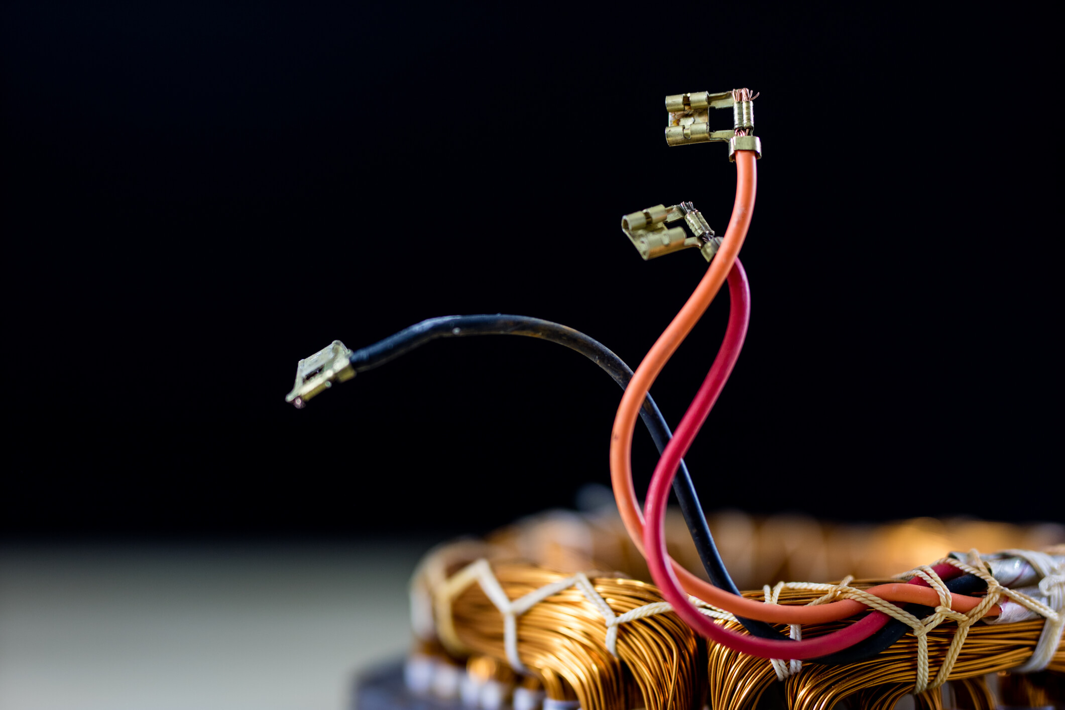
Flyback transformers offer some distinct advantages over other converters because they are:
- Safer due to their circuit isolation that prevents electrical hazards
- Smaller, lighter, and easier to install
- More convenient since one control can separate and operate multiple output voltages
- Less expensive because they contain fewer components
Details of How Flyback Transformers Work
The key components of a flyback transformer include a primary switch, mutually coupled inductor, output rectifier, and input/output capacitors. But before we get into the deeper details of how flyback transformers work, here’s a quick-and-dirty explanation:
- When the primary switch is turned on, it amplifies electronic signals within the device, and the energy is stored within the transformer.
- When the primary switch is turned off, the transformer current is allowed to flow, and voltage is generated and coupled with high-frequency currents.
Now here’s a more detailed explanation for how a flyback transformer works:
- A switch has three terminals that modify the intensity of electronic signals and redirect them either through the:
- Primary coil so it can be stored in the core via closed switch
OR
-
- Secondary coil to be transmitted to the output load via open switch
The output voltage modifies when the duty cycles and turn ratios are adjusted between the primary and secondary coils.
- A coupled inductor is formed by the primary and secondary coils linked by mutual electromagnetic inductance. The purpose of this is to modify voltage and, importantly, isolate circuit components.
- An output diode gets the distributed energy and ensures the electrical current flows steadily and unidirectionally to achieve the necessary voltage.
- Input/output capacitors store energy to be released in controlled and managed amounts to maintain smooth energy flow.
Because flyback transformers are available in many different designs and configurations, it’s important to know exactly what you need before selecting or manufacturing flyback transformers for your application.
Still Have Questions about How a Flyback Transformer Works?
With 70+ years in the electronics contract manufacturing industry, you can be assured we know what we’re talking about when it comes to flyback transformers. Bring us your questions, and we’ll help you understand exactly what is needed to get your design up and running to your exact specifications.
Contact Schott today to get started!